Texture Patterns
You can use the built-in texture pattern generators to create interesting color maps, normal maps, and ORM maps for your materials.
Continuing "Hello Cube"
In the "Hello Cube" example we created a simple color map with a maroon colour:
using var colorMap = materialBuilder.CreateColorMap(StandardColor.Maroon);
You can try out the examples below by simply replacing the colorMap with some more interesting patterns!
If you're feeling adventurous you can also experiment with adding a normalMap and even an ormMap to the cube's material too.
What are Color, Normal, and ORM Maps?
A 'map' is ultimately just 2D texture/bitmap, and all three map types (color, normal, ORM) work together to form a single material.
A color map is the texture that provides the surface colors (sometimes known as the 'albedo' or 'diffuse') for the material.
A normal map is the texture that affects how lighting bounces off the material surface by defining which direction each pixel "faces" relative to the flat surface. Normal maps can be used to give the illusion of surface 'texture' or detail without actually having to modify the polygon mesh (a huge performance improvement).
An ORM map is actually three values baked in to one texture, and is used to add additional information about the nature of the material surface:
-
The Occlusion channel is stored in the Red pixel data of the texture and defines on a scale of 0.0 to 1.0 how much ambient light reflects off each pixel on the material surface. For example, if you're trying to simulate a surface of wooden boards, it's likely that less light will reach in the crevices between the boards than on the surface of the boards themselves.
-
The Roughness channel is stored in the Green pixel data of the texture and defines on a scale of 0.0 to 1.0 how 'rough' the material is at each pixel of its surface. This value is used to determine how 'shiny' the light reflections are on each part of the surface.
-
The Metallic channel is stored in the Blue pixel data of the texture and defines on a scale of 0.0 to 1.0 how 'metallic' the material is at each pixel of its surface. In reality, most materials' surfaces' texel data should always be 0.0 (non-metallic) or 1.0 (metallic). This value is used to determine how reflections and lighting interacts with the surface.
For more information, see: Materials
All texture patterns can be created by using the static methods on the TexturePattern class, located in the Egodystonic.TinyFFR.Assets.Materials namespace.
Any type of map can be created with any pattern type, it just depends what type of value you specify for the pattern's "value" arguments:
- For color maps, you should make a texture pattern of
ColorVects. - For normal maps, you should make a texture pattern of
SphericalTranslations. - For occlusion, roughness, or metallic maps, you should make a texture pattern of
Reals.
Examples using each of these types follow below:
Chequerboard Color Maps#
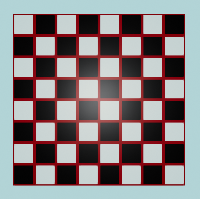
Chequerboard texture pattern
For this first example, we will create a color map using a ChequerboardBordered texture pattern:
using var colorMap = materialBuilder.CreateColorMap(
    TexturePattern.ChequerboardBordered(
        borderValue: ColorVect.FromRgb24(0x880000), // (1)!
        borderWidth: 8, // (2)!
        firstValue: ColorVect.White, // (3)!
        secondValue: ColorVect.Black, // (4)!
        repetitionCount: (8, 8), // (5)!
        cellResolution: 120 // (6)!
    )
);
-
This line is setting the colour of the chequerboard borders.
ColorVect.FromRgb24()allows you to specify colours as hex codes. You can also create aColorVectfrom hue/saturation/lightness usingColorVect.FromHueSaturationLightness(), or specify the RGB components directly by using the constructor (i.e.new ColorVect(r, g, b)). -
This line sets the width of the border around each cell (square), in pixels.
-
This is setting the colour of the first cell (square) and every even-numbered cell after that.
-
This is setting the colour of the second cell (square) and every odd-numbered cell after that.
-
This is setting the number of repetitions (i.e. the grid size of the texture). We want an 8x8 board so we specify repetition count as
(8, 8).Note: In actuality, the type of the expression
(8, 8)is ValueTuple<int, int>. The tuple is being implicitly converted to anXYPair<int>, which a TinyFFR type thatrepetitionCountis declared as. -
This is setting the size, in pixels, of the width and depth of each cell (square).
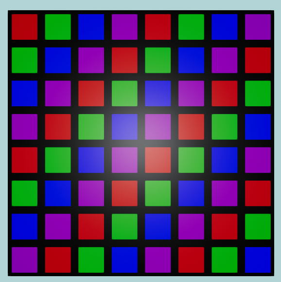
There are some overloads of ChequerboardBordered that can take a thirdValue and/or fourthValue too if you prefer. Here's another example using four colours and an uneven repetition count:

Four colours picked at random, uneven repetition count
using var colorMap = materialBuilder.CreateColorMap(
    TexturePattern.ChequerboardBordered(
        borderValue: ColorVect.RandomOpaque(),
        borderWidth: 16,
        firstValue: ColorVect.RandomOpaque(),
        secondValue: ColorVect.RandomOpaque(),
        thirdValue: ColorVect.RandomOpaque(),
        fourthValue: ColorVect.RandomOpaque(),
        repetitionCount: (10, 6),
        cellResolution: 200
    )
);
There is also a variant pattern called Chequerboard (instead of ChequerboardBordered) that does not include a border:
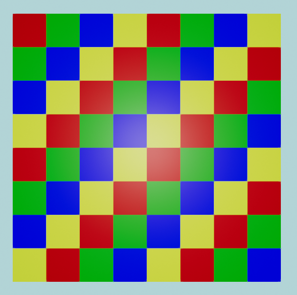
Red / yellow / green / blue, no border
using var colorMap = materialBuilder.CreateColorMap(TexturePattern.Chequerboard(
    firstValue: ColorVect.FromStandardColor(StandardColor.Red), // (1)!
    secondValue: ColorVect.FromStandardColor(StandardColor.Green),
    thirdValue: ColorVect.FromStandardColor(StandardColor.Blue),
    fourthValue: ColorVect.FromStandardColor(StandardColor.Yellow)
));
-
ColorVect.FromStandardColor()can also be replaced with just an implicit conversion fromStandardColor, e.g. you can write this line simply as:firstValue: StandardColor.Red,
Circle or Rectangle Color Maps#
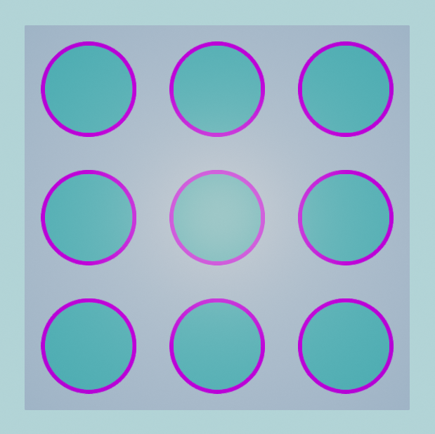
Nine bordered circles
In this example, we create a 3x3 'grid' of bordered circles. We specify each colour in HSL format with the static method ColorVect.FromHueSaturationLightness(). The first argument to FromHueSaturationLightness() is a hue angle in degrees, the second is a saturation (from 0.0 to 1.0), and the third is a lightness (also from 0.0 to 1.0):
using var colorMap = materialBuilder.CreateColorMap(TexturePattern.Circles(
    interiorValue: ColorVect.FromHueSaturationLightness(180f, 0.6f, 0.33f), // (1)!
    borderValue: ColorVect.FromHueSaturationLightness(-70f, 1f, 0.5f), // (2)!
    paddingValue: ColorVect.FromHueSaturationLightness(240f, 0.3f, 0.7f), // (3)!
    repetitions: (3, 3) // (4)!
));
- This is the colour of the interior of each circle.
- This is the colour of the border of each circle.
- This is the colour between the circles.
- Just like with the chequerboard patterns, this specifies the number of circles in each direction.
A single bordered circle with interpolated colouring
Some of the overloads for TexturePattern.Circle() work with interpolatable values (ColorVect is interpolatable). In the following example, we will set colour values for the top, left, right, and bottom of the border and interior of a circle, and the texture pattern will interpolate values around the circle between those four "stops".
This example also uses some slightly more complicated constructions for ColorVects:
- As we saw in the previous example, we can specify colours in HSL format. The first argument to
ColorVect.FromHueSaturationLightness()is the hue angle. - To make our interpolated colour wheel look nice, we set the right, top, left and bottom hue angles by converting them from corresponding
Orientation2Dvalues.Orientation2Dis an enum that represents some base axes in 2D, and we can convert anOrientation2Dto anAnglewith the methodToPolarAngle(). ToPolarAngle()can returnnullif we invoke it onOrientation2D.None, but as we know we are not trying to convert aNoneorientation to an angle, we can use the null-forgiving operator and assume there's aValue.
var rightAngle = Orientation2D.Right.ToPolarAngle()!.Value;
var topAngle = Orientation2D.Up.ToPolarAngle()!.Value;
var leftAngle = Orientation2D.Left.ToPolarAngle()!.Value;
var bottomAngle = Orientation2D.Down.ToPolarAngle()!.Value;

using var colorMap = materialBuilder.CreateColorMap(TexturePattern.Circles(
    interiorValueRight: ColorVect.FromHueSaturationLightness(rightAngle, 1f, 0.3f),
    interiorValueTop: ColorVect.FromHueSaturationLightness(topAngle, 1f, 0.3f),
    interiorValueLeft: ColorVect.FromHueSaturationLightness(leftAngle, 1f, 0.3f),
    interiorValueBottom: ColorVect.FromHueSaturationLightness(bottomAngle, 1f, 0.3f),

    borderValueRight: ColorVect.FromHueSaturationLightness(rightAngle + 90f, 1f, 0.5f), // (1)!
    borderValueTop: ColorVect.FromHueSaturationLightness(topAngle + 90f, 1f, 0.5f),
    borderValueLeft: ColorVect.FromHueSaturationLightness(leftAngle + 90f, 1f, 0.5f),
    borderValueBottom: ColorVect.FromHueSaturationLightness(bottomAngle + 90f, 1f, 0.5f),

    paddingValue: ColorVect.White.WithLightness(0.2f), // (2)!

    repetitions: (1, 1)
));
- Notice that we're shifting the hue colour angle for each border stop by 90°, mostly to help it stand out from the interior colour wheel.
WithLightness()returns a newColorVectwith the HSL lightness adjusted to the given value (in this case we're returningWhitewith a lightness of0.2).
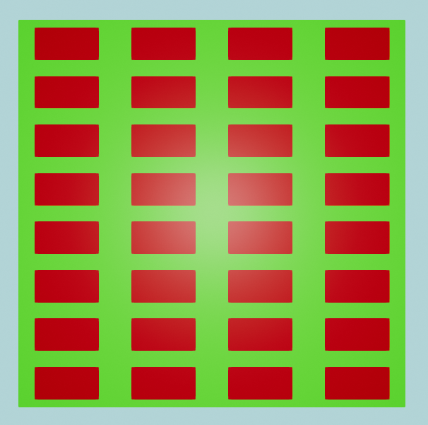
A very simple repetition of red rectangles on a green background
This example shows how to generate a rectangles pattern using only two arguments. If desired, it's also possible to specify a borderValue, but this is optional:

Four squares each with multi-coloured borders
Not only can you specify a border for each "rectangle", but you can actually specify a different value for the top, left, bottom and right sides (optionally):
using var colorMap = materialBuilder.CreateColorMap(
    TexturePattern.Rectangles(
        interiorSize: (64, 64),
        borderSize: (8, 8),
        paddingSize: (32, 32),
        interiorValue: new ColorVect(1f, 1f, 1f),
        borderRightValue: new ColorVect(1f, 1f, 0f),
        borderTopValue: new ColorVect(1f, 0f, 0f),
        borderLeftValue: new ColorVect(0f, 1f, 0f),
        borderBottomValue: new ColorVect(0f, 0f, 1f),
        paddingValue: new ColorVect(0f, 0f, 0f),
        repetitions: (2, 2)
    )
);
Circle or Rectangle Normal Maps#
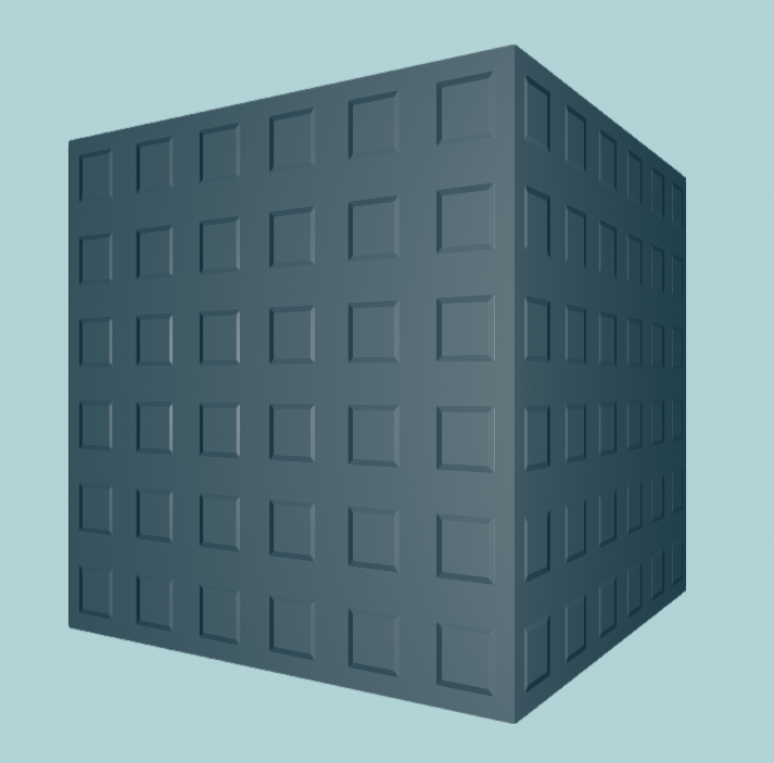
This cube has a flat color map but the normal map gives it the impression of having 'studs' on its surface
Normal maps are textures, but instead of the pixels representing colours (RGB) they represent directions (XYZ). In the real world, most surfaces aren't perfectly flat but actually have slight grooves and imperfections. Normal maps attempt to model those imperfections and patterns by specifying the direction each pixel of the surface is facing (relative to the overall surface plane) and are used when calculating lighting reflections to provide a more realistic-looking material. That means we can make "interesting" normal maps by specifying some pixels that don't face perfectly forward (relative to the surface).
Why are they called 'normal' maps?
You might be confused if you've never come across this terminology before, and be wondering if there's such a thing as an "abnormal" map or a "weird" map. But be assured, no such thing exists.
In math/geometry, a normal vector is the name given to the vector (e.g. arrow) that points exactly perpendicularly out from a surface. This represents exactly what we're trying to model with a normal map: We want a texture that describes how our surface/material is deformed on the per-pixel level, for more realistic lighting.
The term "normal" ultimately comes from Latin; a "norma" was a carpenter's tool for making right-angles.
Normal maps in TinyFFR can be generated with SphericalTranslation texture patterns.
What is a 'SphericalTranslation' in a normal map pattern?
Each SphericalTranslation is comprised of two angle parameters: An AzimuthalOffset and a PolarOffset.
Any value greater than 0° for PolarOffset (the second parameter) will "bend" the texture normal towards the direction determined by the AzimuthalOffset (the first parameter).
-
The first parameter (
AzimuthalOffset) can be any angle and it represents the 2D orientation of the texel's normal direction. In other words, this parameter specifies the direction of distortion on the surface.The mapping of angle to actual world direction depends on the mesh you're using(1) and any rotation of the model instance. For a non-rotated
Cuboidbuilt using the standard method shown previously in "Hello Cube" the standard convention applies(2).-
A value of
0°points along the mesh's "U" axis (also known as its tangent direction).A value of
90°points along the mesh's "V" axis (also known as its bitangent direction).See Meshes for more information on U/V axes.
-
So, for a standard
Cuboidmesh,0°means the normal points rightward,90°upward,180°leftward, and270°downward along the surface.
-
-
The second parameter (
PolarOffset) should be an angle between0°and90°and it represents how distorted the surface is.A value of
0°means the texel normal direction will point perfectly straight out from the surface (indicating a perfectly flat surface at this point).A value of
90°means the texel normal direction will be completely flattened against the surface (indicating a 100% distorted surface).
For this first example, we will create a normal map that gives the impression of rectangular 'studs' sticking out of our surface by using the Rectangles texture pattern:
using var normalMap = materialBuilder.CreateNormalMap(TexturePattern.Rectangles(
    interiorSize: (64, 64),
    borderSize: (8, 8),
    paddingSize: (32, 32),
    interiorValue: new SphericalTranslation(0f, 0f), // (1)!
    borderRightValue: new SphericalTranslation(0f, 45f), // (2)!
    borderTopValue: new SphericalTranslation(90f, 45f),
    borderLeftValue: new SphericalTranslation(180f, 45f),
    borderBottomValue: new SphericalTranslation(270f, 45f),
    paddingValue: new SphericalTranslation(0f, 0f),
    repetitions: (6, 6)
));
-
The
interiorValueandpaddingValuespecify the value in this pattern for all texels inside and outside the rectangle borders respectively.In this case, we want to specify that these interior and padding texels are perfectly flat (non-distorted), so we specify the
SphericalTranslation'sPolarOffsetas 0°. -
We specify each border direction's coordinate
AzimuthalOffsetas being 90° offset from the previous (e.g. right is 0°, top is 90°, left is 180°, bottom is 270°).We then make these border texels point exactly 45° out from the surface by setting their
PolarOffsets to 45°.
To use it, the normalMap is supplied to CreateOpaqueMaterial() alongside your colorMap:
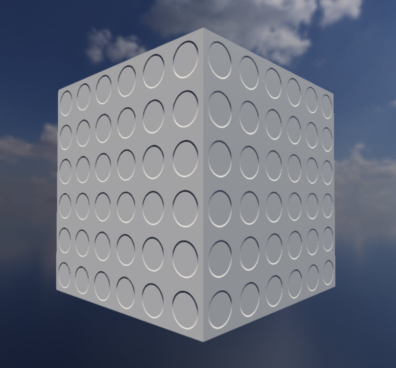
This surface shows circular indentations.
Like with the Interpolated Circle example above we use the interpolatable functionality of SphericalTranslation to create a smooth interpolated circle:
using var normalMap = materialBuilder.CreateNormalMap(TexturePattern.Circles(
    interiorValue: new SphericalTranslation(0f, 0f), // (1)!
    borderValueRight: new SphericalTranslation(180f, 45f), // (2)!
    borderValueTop: new SphericalTranslation(270f, 45f),
    borderValueLeft: new SphericalTranslation(0f, 45f),
    borderValueBottom: new SphericalTranslation(90f, 45f),
    paddingValue: new SphericalTranslation(0f, 0f),
    repetitions: (6, 6)
));
-
The
interiorValueandpaddingValuespecify the value in this pattern for all texels inside and outside the circle borders respectively.In this case, we want to specify that these interior and padding texels are perfectly flat (non-distorted), so we specify the
SphericalTranslation'sPolarOffsetas 0°. -
We specify each border direction's coordinate
AzimuthalOffsetas being one of the 90° right-angle values.We deliberately flip the top/bottom and left/right borders from the usual convention in order to create an "indented" rather than "outdented" effect.
Compare also to Occluded Circular Divots below.
Line & Circle ORM Maps#
The lines along this surface alternate between metallic and non-metallic strips.
In this first example for ORM maps, we will specify just a metallic pattern. Specifically, we will use the Lines pattern to create metallic 'bands'/'strips' horizontally across our material surface:
var metallicPattern = TexturePattern.Lines<Real>( // (1)!
    firstValue: 0f, // (2)!
    secondValue: 1f, // (3)!
    horizontal: true, // (4)!
    numRepeats: 5 // (5)!
);

using var ormMap = materialBuilder.CreateOrmMap(metallicPattern: metallicPattern); // (6)!

using var material = materialBuilder.CreateOpaqueMaterial( // (7)!
    colorMap: colorMap,
    ormMap: ormMap
);
-
We must specify that this is a pattern of
Realvalues (which is the type of value used to create metallic, roughness, or occlusion patterns).Why Real instead of just float?
Realis a TinyFFR type that thinly wraps floating point values with implicit conversions to and fromfloat. Its name comes from the mathematical terminology for a real number (which is what floating point values represent).Realimplements our interpolatable interface (IInterpolatable<>) which means we can use it in patterns that interpolate (like the interpolated circle example above).Eventually, when C# gets a way to implement interfaces on pre-existing types (i.e. via a 'shapes' or 'extension everything' proposal), we may be able to do away with
Realentirely.You could also rely on type inference instead of specifying the type parameter explicitly if you specify your values (e.g.
firstValue,secondValue, etc.) asRealrather thanfloat; but the approach shown in the example tends to be cleaner. -
A value of
0findicates that the first line in our pattern will be non-metallic. -
A value of
1findicates that the second line in our pattern will be metallic.Remember, metallic-map values should generally always only consist of 0f and 1f. Interim values are valid and defined behaviour, but are only really useful for special effects and transitions. A material can't really be "half-metallic" in the real world, and in a rendering context it tends to look odd.
-
This makes our lines horizontal. If you specify
falsefor this parameter, the lines will be vertical instead. -
This indicates how many times we'd like the pattern to repeat (i.e. how many times we want our
firstValueandsecondValueto band across the texture).Because we wrote
5, we will see 10 bands in total (5 offirstValue/non-metallic and 5 ofsecondValue/metallic). -
When creating an ORM map there are three optional parameters; one each for occlusion, roughness, and metallicness.
If you just want to specify a metallic pattern like we're doing here, you can explicitly name the
metallicPatternargument. The library will fill in sensible defaults for you for the roughness and occlusion. -
Finally we pass our
ormMaptoCreateOpaqueMaterial()just like we did with thecolorMapandnormalMap.If you're not passing in a
normalMapmake sure you explicitly name the arguments to the method like we're doing here to make sure you don't accidentally pass yourormMapas anormalMap.
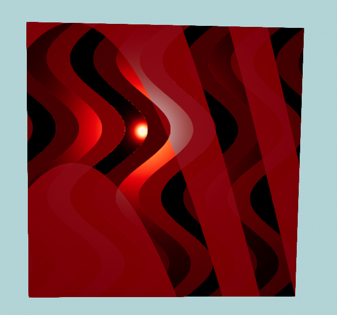
The larger lines are metallic and non-metallic bands. The thinner lines vary in their roughness value.
Example is shown on a cube that is slightly rotated to best show off lighting at an oblique angle.
In this next example we will:
- Create a metallic pattern with curved lines,
- Create a roughness pattern with wavy lines,
- Overlay them over each other in to one ORM map.
Reminder: Flat Colouring
For this example, we have specified a simple flat colour map ("maroon").
All the striations and banding effects shown in this example are just a result of defining differing values for the roughness and metallicness of our material. The underlying colour is all just maroon (dark red).
Perturbation is an optional parameter to the Lines texture pattern that applies a sinusoidal (wave-like) distortion to the lines. There are two parameters to the texture pattern that affect perturbation:
-
perturbationMagnitude -
Defines how 'deep' the curves/waves are.
A value of
0fmeans no perturbation (this is the default). Generally speaking, values between0fand0.5fwill look the best, but any value is permitted.Higher values can start to simulate other materials like wood grains.
Negative values have all the same properties as positive values but reverse the direction of the waves.
-
perturbationFrequency -
Defines how many times the waves/curves will repeat.
Any value is permitted. Values above
1fmake wave patterns, values below1fsimply distort the lines in to a curve shape.Negative values have all the same properties as positive values but reverse the direction of the curves.
var roughnessPattern = TexturePattern.Lines<Real>( // (1)!
    firstValue: 0f,
    secondValue: 0.7f,
    thirdValue: 0.3f,
    fourthValue: 1f,
    horizontal: false,
    numRepeats: 3,
    perturbationMagnitude: 0.1f,
    perturbationFrequency: 2f
);
var metallicPattern = TexturePattern.Lines<Real>(
    firstValue: 0f,
    secondValue: 1f,
    horizontal: true,
    numRepeats: 1,
    perturbationMagnitude: 2f,
    perturbationFrequency: -0.3f
);

using var ormMap = materialBuilder.CreateOrmMap( // (2)!
    roughnessPattern: roughnessPattern,
    metallicPattern: metallicPattern
);
-
This line pattern uses four values to specify four roughness bands (
0fis perfectly smooth,1fis maximally rough).Linepatterns can have up to ten values. -
In this example we're passing in a roughness and metallic map to
CreateOrmMap(). Make sure you name the arguments to avoid accidentally specifying the wrong type of pattern or map.

This surface shows circular divots where the interior of each divot has some ambient occlusion applied to dim the ambient lighting from the skybox.
This example builds on Circular Indents above and adds some ambient occlusion inside the circular divots for additional realism.
As a reminder, the actual surface geometry has not changed (it's still a plain cube mesh); but by clever usage of normal and occlusion mapping we can give the strong "effect" of surface detail.
var normalMap = MaterialBuilder.CreateNormalMap(TexturePattern.Circles( // (1)!
    interiorValue: new SphericalTranslation(0f, 0f),
    borderValueRight: new SphericalTranslation(180f, 45f),
    borderValueTop: new SphericalTranslation(270f, 45f),
    borderValueLeft: new SphericalTranslation(0f, 45f),
    borderValueBottom: new SphericalTranslation(90f, 45f),
    paddingValue: new SphericalTranslation(0f, 0f),
    repetitions: (6, 6)
));

var ormMap = MaterialBuilder.CreateOrmMap( // (2)!
    occlusionPattern: TexturePattern.Circles<Real>(
        interiorValue: 0.5f,
        borderValue: 0.75f,
        paddingValue: 1f,
        repetitions: (6, 6)
    )
);
-
The normal pattern is identical to the one shown above in the Circular Indents example.
-
We make a
Circlespattern with the same dimensions/repetition count as our normal map, but specify the interiors of the circles as having 50% ambient reflectivity, the borders/rims as having 75%, and the outsides of the circles as having the standard 100%.
Plain Fills & Gradients#
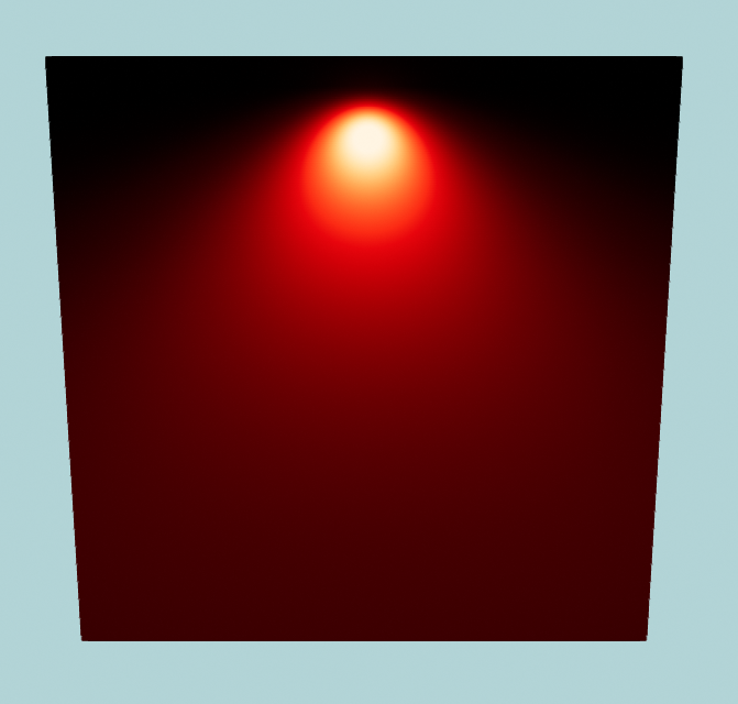
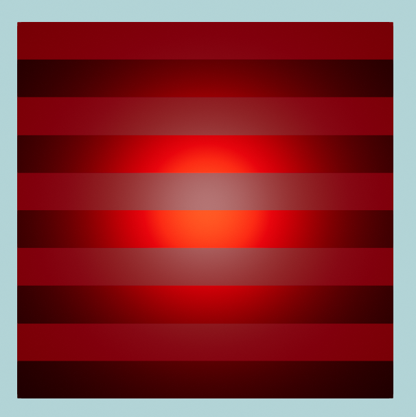
A single light is shining against this dark-red metal cube.
The metal is shiniest at the top and rougher at the bottom.
The last two types of pattern currently supported are PlainFills and Gradients.
In this example we will use a PlainFill to create a fully metallic surface, and then use a GradientVertical to vary the roughness from top-to-bottom:
using var ormMap = materialBuilder.CreateOrmMap(
    roughnessPattern: TexturePattern.GradientVertical<Real>(0f, 1f), // (1)!
    metallicPattern: TexturePattern.PlainFill<Real>(1f) // (2)!
);

using var material = materialBuilder.CreateOpaqueMaterial(
    colorMap: colorMap,
    ormMap: ormMap
);
- This creates a vertical gradient from 0 (smooth) to 1 (rough) for the
roughnessPattern. - This sets a plain fill of 1 (metal) for the whole
metallicPattern.
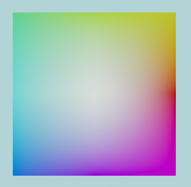
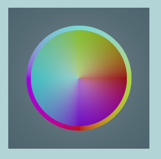
Rainbow color map created with a gradient texture pattern.
This example shows how to use the Gradient() pattern to create a rainbow color map. We're adjusting the hue angle for each colour by 45 degrees as we go around the 'circle' of the gradient:
using var colorMap = materialBuilder.CreateColorMap(
    TexturePattern.Gradient(
        right:          ColorVect.FromHueSaturationLightness(0f, 1f, 0.5f),
        topRight:       ColorVect.FromHueSaturationLightness(45f, 1f, 0.5f),
        top:            ColorVect.FromHueSaturationLightness(90f, 1f, 0.5f),
        topLeft:        ColorVect.FromHueSaturationLightness(135f, 1f, 0.5f),
        left:           ColorVect.FromHueSaturationLightness(180f, 1f, 0.5f),
        bottomLeft:     ColorVect.FromHueSaturationLightness(225f, 1f, 0.5f),
        bottom:         ColorVect.FromHueSaturationLightness(270f, 1f, 0.5f),
        bottomRight:    ColorVect.FromHueSaturationLightness(315f, 1f, 0.5f),
        centre:         ColorVect.White
    )
);
using var material = materialBuilder.CreateOpaqueMaterial(colorMap);
Gradient and Plain Fill Pattern Types
There are multiple variants of Gradient/fill patterns available:
-
PlainFill() -
The plain fill pattern does as its name implies. It takes a single argument that is the value for the full color, normal, occlusion, roughness, or metallic map.
In the first example we're using it to create a metallic map that makes our material fully metallic all over.
-
GradientVertical() -
This pattern interpolates between a
topandbottomvalue and produces a vertical gradient.It can also take an optional
centrevalue if you wish for a skewed/non-linear gradient. -
GradientHorizontal() -
This pattern interpolates between a
leftandrightvalue and produces a horizontal gradient.It can also take an optional
centrevalue if you wish for a skewed/non-linear gradient. -
GradientRadial() -
This pattern interpolates between an
innerandoutergradient and produces a radial (circular) gradient.You can also specify whether to
fringeCorners, i.e. whether the corners of the resultant map texture should go a little past theoutervalue. Iftruethe corners of the map will 'fringe' pastouter. Iffalsethe corners will be clamped to theoutervalue. -
Gradient() -
Finally, this more general purpose gradient pattern lets you specify a value at nine different points (the four corners, the four sides, and the centre).
The pattern will interpolate between all nine values across the map texture.
Transforms#
Finally, every texture pattern (except PlainFill) takes a Transform2D parameter named transform that can be used to apply a rescaling, rotation, and shifting/movement to the final texture pattern.
- A
scalingwill take the pattern and shrink or expand it. - A
rotationwill take the pattern and rotate it. - A
translationwill take the pattern and shift/move it. -
You can supply any one of these "transformations", or all three, or anything in between(1).
-
When supplying more than one type of transformation, they will always be applied in a specific order:
- Scaling first,
- Then rotation,
- Then translation.
-
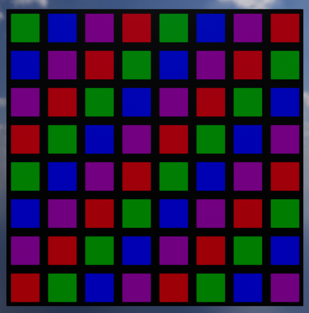
We will start off with this untransformed color map:
using var colorMap = materialBuilder.CreateColorMap(
    TexturePattern.ChequerboardBordered<ColorVect>(
        borderValue: StandardColor.Black,
        firstValue: StandardColor.Red,
        secondValue: StandardColor.Green,
        thirdValue: StandardColor.Blue,
        fourthValue: StandardColor.Purple,
        borderWidth: 8,
        transform: Transform2D.None // (1)!
    )
);
-
Only this line will change in the following three examples.
(Supplying
Transform.Noneto thetransformargument is the same as supplying no argument at all.)
This color map has a transform of None applied, i.e. no transformation is made.
The tabs below show the three different transformation types being applied to it:
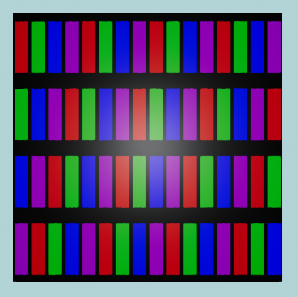
Scaling transform applied to the original color map.
In this example we apply a scaling transformation of 50% in the horizontal direction and 200% in the vertical direction:
using var colorMap = materialBuilder.CreateColorMap(
    TexturePattern.ChequerboardBordered<ColorVect>(
        borderValue: StandardColor.Black,
        firstValue: StandardColor.Red,
        secondValue: StandardColor.Green,
        thirdValue: StandardColor.Blue,
        fourthValue: StandardColor.Purple,
        borderWidth: 8,
        transform: new Transform2D(scaling: (0.5f, 2f)) // (1)!
    )
);
- This transform is specifying a 0.5x scaling in the X (horizontal) direction and a 2.0x scaling in the Y (vertical) direction.
Why does scaling down the horizontal size increase the number of columns etc.?
This may or may not confuse you depending on your perception of the scaled image, but if it does confuse you, here's the explanation:
Somewhat counterintuitively, decreasing the horizontal (X-axis) scaling of the pattern to 50% has doubled the number of columns we see. Similarly, increasing the vertical (Y-axis) scaling to 200% has halved the number of rows.
Nonetheless, this is correct. Here's the explanation of what a scaling transform is doing:
- Imagine a scaling factor less than
1.0fas like a vice grip 'squashing' the image. In this example we've 'squashed' the pattern along its X-axis to half its original width. The squashed pattern then simply repeats over and over left-to-right. - Imagine a scaling factor greater than
1.0flike a pinch-and-zoom-in effect on the image. In this example we've 'expanded' the pattern along its Y-axis to double its original height. The bottom half of the expanded pattern is then lost past the bottom of our image.
Another way to think of it is simply consider the size of each original square in the original, unscaled chequerboard pattern. Now look at what's happened to the size of each square post-scaling: Each square has become 50% as wide but 200% as tall.
Negative scaling factors
You can also flip the outcome (i.e. mirror the image vertically or horizontally) by supplying a negative scaling factor.
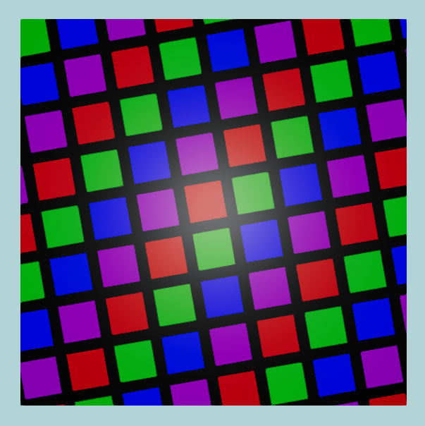
Rotation transform applied to the original color map.
In this example we apply an anticlockwise rotation transform of 10°:
using var colorMap = materialBuilder.CreateColorMap(
    TexturePattern.ChequerboardBordered<ColorVect>(
        borderValue: StandardColor.Black,
        firstValue: StandardColor.Red,
        secondValue: StandardColor.Green,
        thirdValue: StandardColor.Blue,
        fourthValue: StandardColor.Purple,
        borderWidth: 8,
        transform: new Transform2D(rotation: 10f) // (1)!
    )
);
- This transform is specifying a 10 degree rotation in the anticlockwise direction.
Clockwise Rotations
You can rotate clockwise by supplying a negative value for rotation in your transform.
The reason positive values result in an anticlockwise rotation in TinyFFR is just a convention, although it's worth noting this is ultimately just conforming to a general convention in trigonometry.
Translation transform applied to the original color map.
In this example we shift the pattern right by 1/8 and down by 1/4:
using var colorMap = materialBuilder.CreateColorMap(
    TexturePattern.ChequerboardBordered<ColorVect>(
        borderValue: StandardColor.Black,
        firstValue: StandardColor.Red,
        secondValue: StandardColor.Green,
        thirdValue: StandardColor.Blue,
        fourthValue: StandardColor.Purple,
        borderWidth: 8,
        transform: new Transform2D(translation: (1f / 8f, -1f / 4f)) // (1)!
    )
);
- This transform is specifying a positive shift of one eighth in the X/U direction and a negative shift of one quarter in the Y/V direction.
The translation values for X and Y are specified as fractions of the entire pattern's width/height respectively, so usually you'll want to supply values in the range [-1, 1] (though any valid float is permitted).
As per the usual convention a positive X value shifts right and a positive Y value shifts upward.