Meshes
A mesh is a set/group of polygons defining the shape of a 3D object. Meshes do not define the surface material of an object, only its polygonal layout.
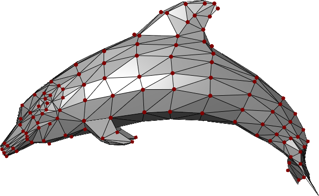
This example shows multiple triangular polygons connected together to define the mesh shape of a dolphin.
Every polygon is defined by a set of three vertices (vertices here are the dark-red dots).
MeshVertex & VertexTriangle#
In TinyFFR, every mesh is comprised of a list of MeshVertex values and a list of VertexTriangle values together.
The MeshVertex list simply specifies every vertex in the mesh (the red dots in the image above). It does not make any connection between them.
The VertexTriangle list details how to connect those vertices in to triangular polygons.
MeshVertex#
Each MeshVertex has the following properties:
- Location This is the position of the vertex relative to all others and relative the implied mesh centre-point at
(0, 0, 0). - TextureCoords This is the UV map co-ordinates for the surface at this point, i.e. it specifies where on any texture applied to the surface of the mesh this vertex maps to. A value of
(0f, 0f)indicates that this vertex maps to the bottom-left corner of a given texture; a value of(1f, 1f)maps to the top-right corner, etc. Does not need to be in the range(0f, 0f)to(1f, 1f); texture wrapping is applied automatically. - TangentRotation In a nutshell, this quaternion is used in tangent-space to rotate the positive-U axis to the tangent vector; from which the bitangent and normals are calculated.
The TangentRotation is a Quaternion and is not intuitive to understand; so a static method on MeshVertex is provided to help create it(1):
- Additionally, an overloaded constructor for
MeshVertexcan take the three arguments to this static method and invoke it for you at construction time.
-
CalculateTangentRotation(Direction tangent, Direction bitangent, Direction normal) -
Pass the
tangent,bitangent, andnormalfor your vertex to this method and it will generate the correctTangentRotationfor you.- The tangent is the direction that points along the positive-U axis; that is the direction where the texture co-ordinates
Uvalue increases. - The bitangent is the direction that points along the positive-V axis; that is the direction where the texture co-ordinates
Vvalue increases. - The normal is the direction facing exactly perpendicularly away from the surface being described at this vertex, away from the front face of the surface.
A diagram of these three values is shown for the highlighted vertex below:
- The tangent is the direction that points along the positive-U axis; that is the direction where the texture co-ordinates
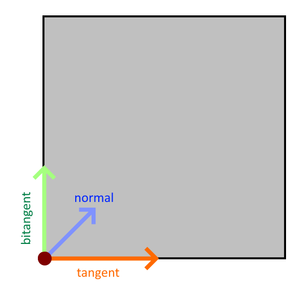
In this crude diagram, imagine we are looking directly at the front face of a cube.
For the highlighted vertex at the bottom left, we show the three directions required for calculating the tangent-frame rotation:
-
The tangent (orange arrow) points along the positive-U axis (this is the direction pointing from left-to-right along any textures mapped to this surface).
-
The bitangent (green arrow) points along the positive-V axis (this is the direction pointing from bottom-to-top along any textures mapped to this surface).
-
The normal (blue arrow) points out of the screen, towards you (this is the direction pointing directly "out", away from the front-face of the surface) (this arrow is not pointing diagonally on the 2D surface, it is pointing up and straight out away from the surface).
VertexTriangle#
With an ordered list (or span) of MeshVertex instances, you can specify the way those vertices combine to form triangles using their indices in that list.
Accordingly, a VertexTriangle has only three properties: IndexA, IndexB, IndexC. Each index is an integer that indexes in to a MeshVertex list/span; together forming one triangle.
The order the vertices are specified in within the triangle is important and define the triangle's winding order. When looking at the visible (front) face of the triangle, the vertices should be specified in an anti-clockwise order (it doesn't matter which one comes first, just the respective order). This is a convention in TinyFFR. If your vertices are specified with a clockwise winding order, the triangle will not be rendered except when looking from the inside out or behind the mesh.
Creating / Importing Meshes#
Meshes can be loaded via the factory's AssetLoader (see Loading Assets) or created from triangles/vertices using the IMeshBuilder interface (found via the factory at factory.MeshBuilder or factory.AssetLoader.MeshBuilder).
MeshReadConfig#
All ways to read mesh data from files have methods that can take a MeshReadConfig. This struct allows you to control how TinyFFR processes the mesh data and has the following properties:
-
FixCommonExportErrors -
Defaults to
true. Set tofalseto stop TinyFFR attempting to fix common mesh data errors (such as in-facing normals, degenerate polygons, etc).You should usually want to keep this as
trueunless you find TinyFFR is "fixing" your mesh incorrectly. -
OptimizeForGpu -
Defaults to
true. Whentrue, TinyFFR will spend some additional time optimizing the mesh data to improve your framerate.Setting this to
falsemay improve load times, but may also have a negative impact on framerate. -
CorrectFlippedOrientation -
Defaults to
true. Whentrue, TinyFFR will correct winding order, normals, tangents, and bitangents if it detects the mesh data has been exported with a flipped orientation.This can happen sometimes if a mesh's data is combined with a negative scaling or mirror transform, etc.
Setting this to
falsewill tell TinyFFR not to attempt this correction (in the case you want to see the data exactly as exported, for example). -
SubMeshIndex -
Defaults to
null. Whennull, if the given asset file contains multiple sub-meshes those meshes will be loaded together and returned to you as a single amalgamated object.If not null, this value specifies which sub-mesh to load. You can determine how many sub-meshes an asset file contains by inspecting the
SubMeshCountof the returnedMeshReadMetadatawhen invokingReadMeshMetadata(). -
LoadSkeletalAnimationDataIfPresent -
Defaults to
true. Whentrue, if the loaded mesh contains skeletal animation bone/node data, that data will be loaded and embedded inside the mesh's vertex structures on the GPU memory. Any animations in the asset file will be accessible via the animation playback system.If this is set to
falseTinyFFR will only load the data as though it were a static mesh. -
AnimationTicksPerSecondOverride -
Defaults to
null. If the loaded mesh contains skeletal animation data (and that data is being loaded), the embedded file's keyframe tick rate will be used to calculate the rate (per-second) at which each animation should play by default. Every file format has a different ticks-to-seconds ratio, and some file formats do not specify it at all (a default of 25 ticks/second is assumed in these scenarios).If this default is incorrect (or you wish to adjust it), you can set this property to any non-null value.
MeshCreationConfig#
All ways to create meshes have methods that can take a MeshCreationConfig. This struct allows you to modify how the mesh is created and has the following properties:
-
FlipTriangles -
Set to
trueto reverse the winding-order of triangles in the mesh (i.e. flip the mesh "inside-out").Most rendering engines (including TinyFFR) employ something called back-face culling, which is a performance optimisation where the rendering of the inside of opaque models is skipped. However, which side of a mesh is its inside, or 'back side', is determined its' polygons'/triangles' winding order.
The convention in TinyFFR is that front-facing polygons should have an anti-clockwise order with respect to the camera. Some exporters may export their models with a clockwise order however; and in this case you can simply flip the triangles by specifying
FlipTriangles = true. -
InvertTextureU -
Set to
trueto swap the direction of textureUco-ordinates by inverting them."Inverting" means flipping the values so that
1fbecomes0f,0.3fbecomes0.7f, and so-on.This may be useful in cases where the mesh has been exported with an inverted/flipped texture-mapping convention. You may need to use this and
InvertTextureVin conjunction withFlipTrianglesfor some meshes to get them to display correctly. -
InvertTextureV -
Set to
trueto swap the direction of textureVco-ordinates by inverting them."Inverting" means flipping the values so that
1fbecomes0f,0.3fbecomes0.7f, and so-on.This may be useful in cases where the mesh has been exported with an inverted/flipped texture-mapping convention. You may need to use this and
InvertTextureUin conjunction withFlipTrianglesfor some meshes to get them to display correctly. -
LinearRescalingFactor -
Resizes the mesh by scaling all vertex
Locations by the given amount (with respect to(0, 0, 0)). This is useful when there may be a mismatch between the units used in the original modelling software and those used by your application.The specified value is a simple linear factor / coefficient of the original imported size:
-
Values greater than
1fwill expand the mesh's size (e.g.1.5fincreases its size by 50%). -
Values less than
1fwill reduce the mesh's size (e.g.0.5fdecreases its size by 50%). -
Negative values also invert the mesh and will generally turn it inside-out.
For example, if a mesh was exported with a size of
1fmeaning 1 foot, but you want1fto mean 1 meter, you could set yourLinearRescalingFactorto1f / 3.28084f.Why only a uniform scalar? Why can I not rescale the mesh differently for each axis?
Only a uniform rescale maintains a mesh's integrity regarding its vertex data.
Although we may think of a polygon mesh as just being points in space, each vertex also generally contains pre-baked data such as tangents, bitangents, normals, and texture U/V data.
A uniform scaling maintains the correctness of this additional data, but non-uniform scaling will break this information. If you need a non-uniform scaling of mesh data, it is best to go back to the authoring program it was originally created with and make the change there.
If you want to non-uniformly rescale model instances after importing the mesh, that is fine and can be done later. This parameter is instead concerned with applying a universal rescale to the imported polygon data.
-
-
OriginTranslation -
Moves all vertices'
Locations by the inverse of this value in order to create a shift of the local origin point.For example, if this value is
(1, 2, 3), all vertexLocations will have(-1, -2, -3)added to them.When placing a model instance in a scene, the mesh's origin point indicates the exact point on that mesh that be positioned at the requested spot in the scene/world.
When rotating and scaling model instances, the underlying mesh's origin point will also be used as the default point around which that model will be transformed. For example, pick up anything around you right now and imagine rotating it in 3D space: You must select a point in or around that object to rotate it around (even if that's simply the centre of that object).
A value of
Vect.Zero(e.g.(0f, 0f, 0f)) makes no adjustment to the mesh's origin point. Otherwise, the specified value moves the origin point in the mesh by the given amount, e.g.(1f, 2f, 3f)moves the origin point by 1 in the X direction, 2 in the Y direction, and 3 in the Z direction.
MeshGenerationConfig#
When generating a mesh from a polygon group or other structure (such as a shape description), you can specify a MeshGenerationConfig that controls how the mesh vertices are generated. This struct has the following properties:
-
TextureTransform -
A
Transform2Dspecifying how to modify theUVs (i.e.TextureCoords) globally across the mesh.The
Translationof the transform is added to everyTextureCoordsvalue. For example, for a given vertex if aTextureCoordspair would have been(0.3f, 0.6f)and theTranslationproperty is(-0.2f, 0.1f), the resultant value will be(0.1f, 0.7f).The
Rotationof the transform rotates everyTextureCoordsvalue around the 2D origin ((0, 0)) anti-clockwise. For example, for a given vertex if aTextureCoordspair would have been(0.3f, 0.6f)and theRotationproperty is90°, the resultant value will be(-0.6f, 0.3f).The
Scalingof the transform has its reciprocal(1) multiplied with everyTextureCoordsvalue. For example, for a given vertex if aTextureCoordspair would have been(0.3f, 0.6f)and theScalingproperty is(2f, 0.1f), the resultant value will be(0.15f, 6f).-
The reciprocal is applied as this is usually what a user actually wants when thinking about scaling UV coords.
For example, scaling a surface dimension by
2ffeels like it should blow the texture up (i.e. "zoom in") to 200% along that axis. To achieve that, we actually have to halve the coords along that axis, hence why we apply the reciprocal.If you don't want this behaviour, specify the reciprocal of your scaling factor in the transform; easily done with the
XYPair<float>.Reciprocalproperty.
-
Using Shape Definitions#
Perhaps the easiest way to create a mesh programmatically is to use a Cuboid to define the overall mesh shape:
_ = meshBuilder.CreateMesh( // (1)!
    new Cuboid(1f, 2f, 3f)
);

_ = meshBuilder.CreateMesh( // (2)!
    new Cuboid(1f, 2f, 3f),
    new Transform2D((0.1f, 0.2f), 90f, (0.5f, 0.75f)),
    centreTextureOrigin: true
);

_ = meshBuilder.CreateMesh( // (3)!
    new Cuboid(1f, 2f, 3f),
    centreTextureOrigin: false,
    new MeshGenerationConfig { TextureTransform = Transform2D.None },
    new MeshCreationConfig { OriginTranslation = new Vect(0.5f) }
);
-
This simple invocation creates a new
Meshin the shape of a 1m x 2m x 3m cuboid.All of the vertices in the resultant mesh will have their texture coords and tangent rotations set to sensible values.
-
This invocation creates a 1m x 2m x 3m cuboid but also specifies a texture transform.
The texture transform defines how the UV-coordinates should be transformed on the surface of the mesh (see above). In this example we:
- Specify a translation (movement) of
0.1ffor surface textures in the X/U direction and0.2fin the Y/V direction; - Specify a rotation of
90°, meaning surface textures will be rotated by 90° anti-clockwise; - Specify a scaling of all surface textures by
0.5f(50%) in the X/U direction and0.75fin the Y/V direction.
We also specify
centreTextureOriginastrue. Whentrue, all textures will have their(0, 0)origin point (e.g. their bottom-left corner) be placed on the centre of each cuboid face. Whenfalse, all textures will have bottom-left corner placed on the bottom-left vertex of each cuboid face. By default this value isfalse. - Specify a translation (movement) of
-
This invocation creates a 1m x 2m x 3m cuboid but specifies the
MeshGenerationConfigandMeshCreationConfigobjects directly.See above for more information on these objects.
Using Polygons#
It is possible to create a mesh using one or more Polygons.
Triangulation
When creating a Mesh using one or more Polygons, the mesh builder will triangulate your polygons for you automatically (triangulation is the process of breaking down the polygon in to VertexTriangles).
Note however that if you specify your vertices in the wrong winding order, or supply degenerate polygons (i.e. polygons with holes, crossing edges, non-coplanar vertices, or fewer than 3 vertices) the call to CreateMesh(...) will throw an exception.
Polygon Struct#
The Polygon struct has the following properties/arguments:
Vertices A ReadOnlySpan<Location> which defines the polygon's points in 3D space.
- All vertices must be coplanar (defined on the same plane through space).
- The vertices are expected to form a complete enclosed polygon. They define the polygon's edges implicitly by their ordering: Each vertex is assumed to form an edge with the next one in the span, and the final vertex is assumed to connect back to the first.
- The polygon is expected to be "simple"; i.e. it does not need to be convex but it is expected that there are no holes and no edges intersect.
Normal The Direction facing "out" or "away from" the front-face of the polygon.
- For example, if the polygon is meant to be viewed by a camera looking forward, the normal should be
Direction.Backward. - The normal should be orthogonal to the plane the vertices are defined on.
IsWoundClockwise A bool indicating whether or not the vertices are specified in a clockwise winding order.
- This order is as-seen when looking at the polygon in the direction opposite to its normal; i.e. when looking directly at its front face.
- By default this is
false. You should specify anti-clockwise polygons when possible as this is the default TinyFFR works with.
It is possible to construct a Polygon without specifying its Normal. The constructor will then use the static method Polygon.CalculateNormalForAnticlockwiseCoplanarVertices() to 'detect' the normal. In some cases using this method may be unavoidable (e.g. if generating polygons dynamically) but this method does have a non-negligible performance cost.
CalculateNormalForAnticlockwiseCoplanarVertices() assumes:
- There are at least three vertices;
- The vertices are coplanar;
- The vertices are specified in an anti-clockwise winding order.
If your vertices do not meet these criteria you must specify the Normal yourself or an exception will be thrown.
Using a Single Polygon#
It's possible to specify a "mesh" using a single polygon. This can be useful for creating camera-facing flat planes and/or "billboards".
var pointsMemory = factory.ResourceAllocator.CreatePooledMemoryBuffer<Location>(4);
var points = pointsMemory.Span; // (1)!
points[0] = new Location(0.5f, -0.5f, 0f); // (2)!
points[1] = new Location(-0.5f, -0.5f, 0f);
points[2] = new Location(-0.5f, 0.5f, 0f);
points[3] = new Location(0.5f, 0.5f, 0f);
var polygon = new Polygon(points, normal: Direction.Backward); // (3)!
using var mesh = meshBuilder.CreateMesh(polygon); // (4)!
factory.ResourceAllocator.ReturnPooledMemoryBuffer(pointsMemory); // (5)!
-
We want to create a mesh that is four vertices defining a square so firstly we rent a 4-length
Locationspan using the factory's Resource Allocator.You could also stackalloc the data in this instance, but for larger polygons you may need heap memory, so we show that example here.
-
Next we define four points in a square formation. We want the square to "face" the forward direction so define them all in the XY plane (Z remains constant).
Note that their ordering is important: We specify them in an anti-clockwise order with respect to our front-face view direction.
-
Here we create our
Polygonstruct, passing in thepointsspan as our vertices andDirection.Backwardas the normal. -
Here we pass the
polygontoCreateMesh(), which returns us a triangulatedMeshresource that has all its vertices'TextureCoords,Location, andTangentRotationproperties set correctly. -
Finally we return the rented
pointsMemoryback to the factory.
The mesh builder picks sensible defaults for you regarding each vertex's TextureCoords. However, if you want more control of how textures/materials are laid out on your polygon surface, you can supply additional arguments to CreateMesh():
using var mesh = meshBuilder.CreateMesh(
    polygon,
    textureUDirection: Direction.Up, // (1)!
    textureVDirection: Direction.Left, // (2)!
    textureOrigin: points[0], // (3)!
    new MeshGenerationConfig { /* generation options here, e.g. texture transform */ },
    new MeshCreationConfig { /* creation options here */ }
);
-
This sets the direction of the positive U axis across the plane of the polygon.
Ideally this value should be orthogonal to the normal (i.e. the direction should be parallel to the polygon plane).
-
This sets the direction of the positive V axis across the plane of the polygon.
Ideally this value should be orthogonal to the normal (i.e. the direction should be parallel to the polygon plane).
-
This sets where on the mesh the texture origin (i.e. the bottom-left corner of any applied texture) should sit.
Using Multiple Polygons#
Of course for most meshes you'll want to specify multiple polygons. For this purpose, the mesh builder provides a specialized collection; IMeshPolygonGroup. You simply add Polygons to the group and then pass the group to a CreateMesh() overload when ready.
IMeshPolygonGroup Memory
It is safe / valid to dispose of any memory in use by Polygons after they're added to the group (the group makes a copy of their data).
This does mean however the memory footprint of a group can get quite large with complex meshes consisting of many vertices.
In order to eliminate GC pressure, the memory internal to a polygon group is pooled; however this means the group must be disposed when no longer needed. Neglecting to dispose the group will cause your application to leak memory.
It is safe to dispose the group after it has been passed to CreateMesh() and you no longer need the data it contains. You should not pass a disposed group to CreateMesh().
Note that after disposal the buffers used by the group may be re-used by another group. Holding on to the reference of a group or continuing to use it in any way after it is disposed is not permitted.
The following example shows how to make a two-sided square:
var polyGroup = meshBuilder.AllocateNewPolygonGroup(); // (1)!

var pointsMemory = factory.ResourceAllocator.CreatePooledMemoryBuffer<Location>(4);
var points = pointsMemory.Span;

points[0] = new Location(0.5f, -0.5f, 0f);
points[1] = new Location(-0.5f, -0.5f, 0f);
points[2] = new Location(-0.5f, 0.5f, 0f);
points[3] = new Location(0.5f, 0.5f, 0f);
polyGroup.Add( // (2)!
    new Polygon(points, normal: Direction.Backward)
);

points[0] = new Location(0.5f, -0.5f, 0f);
points[1] = new Location(0.5f, 0.5f, 0f);
points[2] = new Location(-0.5f, 0.5f, 0f);
points[3] = new Location(-0.5f, -0.5f, 0f);
polyGroup.Add( // (3)!
    new Polygon(points, normal: Direction.Forward),
    textureUDirection: Direction.Left,
    textureVDirection: Direction.Up,
    textureOrigin: points[3]
);

using var mesh = meshBuilder.CreateMesh( // (4)!
    polyGroup,
    new MeshGenerationConfig { /* specify generation options here */ },
    new MeshCreationConfig { /* specify creation options here */ }
);

polyGroup.Dispose();  // (5)!
factory.ResourceAllocator.ReturnPooledMemoryBuffer(pointsMemory);
-
Here we allocate a new polygon group using the mesh builder.
We must remember to dispose the group after creating the mesh.
-
Here, we add a polygon to the polygon group.
One the polygon is added we can re-use its memory (the polygon group takes a copy).
-
Here we add the next polygon to the group.
The
Add()method allows us to specify the texture U/V directions and the texture origin.You may recall these are the same as the optional parameters for defining a single polygon; these arguments set the directions of positive U and positive V for the texture map, and where on the polygon the texture origin should be.
-
Here we pass the polygon group to
CreateMesh(), which will triangulate the whole group and give us back a newMeshresource. -
Finally we must remember to dispose the polygon group as well as returning any rented memory buffers.
Using MeshVertex Spans#
Finally, it's possible to create a mesh directly using a Span<MeshVertex> and Span<VertexTriangle> if you want absolute control of vertex data and triangulation methods.
The following example recreates the single-polygon example from above with "raw" vertices/triangles:
var verticesMemory = factory.ResourceAllocator.CreatePooledMemoryBuffer<MeshVertex>(4);
var trianglesMemory = factory.ResourceAllocator.CreatePooledMemoryBuffer<VertexTriangle>(2);
var vertices = verticesMemory.Span;
var triangles = trianglesMemory.Span;

vertices[0] = new MeshVertex(
    location: (0.5f, -0.5f, 0f),
    textureCoords: (0f, 0f),
    tangent: Direction.Right,
    bitangent: Direction.Up,
    normal: Direction.Backward
);
vertices[1] = new MeshVertex(
    location: (-0.5f, -0.5f, 0f),
    textureCoords: (1f, 0f),
    tangent: Direction.Right,
    bitangent: Direction.Up,
    normal: Direction.Backward
);
vertices[2] = new MeshVertex(
    location: (-0.5f, 0.5f, 0f),
    textureCoords: (1f, 1f),
    tangent: Direction.Right,
    bitangent: Direction.Up,
    normal: Direction.Backward
);
vertices[3] = new MeshVertex(
    location: (0.5f, 0.5f, 0f),
    textureCoords: (0f, 1f),
    tangent: Direction.Right,
    bitangent: Direction.Up,
    normal: Direction.Backward
);

triangles[0] = new(0, 1, 2);
triangles[1] = new(2, 3, 0);

using var mesh = meshBuilder.CreateMesh(
    vertices,
    triangles,
    new MeshCreationConfig { /* specify creation options here */ }
);

factory.ResourceAllocator.ReturnPooledMemoryBuffer(trianglesMemory);
factory.ResourceAllocator.ReturnPooledMemoryBuffer(verticesMemory);
Skeletal Meshes#
It is also possible to manually create skeletal meshes (e.g. meshes with nodes/bones and vertex skinning data + animations); see Animations.
Reading & Modifying Mesh Data#
The factory's AssetLoader lets you read mesh data in to a vertex and triangle buffer. You can use this to modify a loaded mesh's data and then pass it to CreateMesh() in the same way:
var assLoad = factory.AssetLoader;

var meshMetadata = assLoad.ReadMeshMetadata(@"Path\To\mesh.gltf");
var vertexBuffer = factory.ResourceAllocator
    .CreatePooledMemoryBuffer<MeshVertex>(meshMetadata.VertexCount);
var triangleBuffer = factory.ResourceAllocator
    .CreatePooledMemoryBuffer<VertexTriangle>(meshMetadata.TriangleCount);
assLoad.ReadMesh(@"Path\To\mesh.gltf", vertexBuffer.Span, triangleBuffer.Span);

// Modify data in vertexBuffer and triangleBuffer here

using var mesh = assLoad.MeshBuilder.CreateMesh(
    vertexBuffer.Span,
    triangleBuffer.Span,
    new MeshCreationConfig { }
);
factory.ResourceAllocator.ReturnPooledMemoryBuffer(triangleBuffer);
factory.ResourceAllocator.ReturnPooledMemoryBuffer(vertexBuffer);